Alibaba.com Onsite-Verified Supplier Trade Assurance Order Protection [email protected]
🇺🇸 English🇩🇪 Deutsch 🇪🇸 Español🇫🇷 Français 🇵🇹 Português🇮🇹 Italiano 🇷🇺 Русский🇯🇵 日本語 🇰🇷 한국어🇸🇦 العربية 🇹🇷 Türkçe🇳🇱 Nederlands
BLDC Motor Controller PCBA SMT assembly line Shenzhen VUKO Electronics
OEM & ODM Engineering Excellence

BLDC Motor Controller PCBA: Complete OEM/ODM Sourcing & Engineering Guide

Engineered for precision Field-Oriented Control (FOC), high power density, and robust thermal dynamics. Turnkey manufacturing from Shenzhen VUKO Electronics Co., Ltd.

Developing a High-Efficiency Brushless DC Driver? Send Gerber, schematics, and BOM part lists to receive an in-depth DFM check and tiered pricing within 24 hours.
Get a Quote

Core Capabilities in BLDC Controller Manufacturing

FOC & SVPWM

Field-Oriented Control support

Heavy Copper

2 oz to 6 oz power planes

Wide-Bandgap

GaN & SiC power stage options

24h Response

Fast-track DFM & quote analysis

Low MOQ

Prototypes from 5 units

Full Traceability

Lot tracking & 3D AOI/X-ray

Turnkey Sourcing

Authorized tier-1 components

ISO Certified

ISO9001, RoHS, UL 94V-0

Product Architectures

Curated BLDC Motor Controller PCBA Recommendations

From battery-powered micro-mobility to industrial robotic actuation and heavy-duty HVAC compressors, Shenzhen VUKO Electronics Co., Ltd. manufactures application-optimized BLDC driver assemblies tailored to precise thermal, electrical, and mechanical boundaries.

Low-Voltage Precision FOC Driver

12V – 48V / 50A
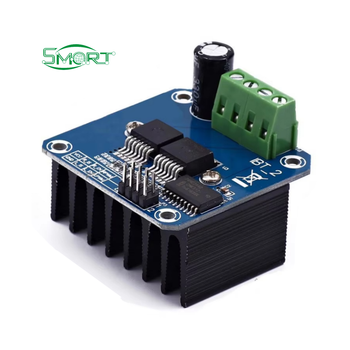
Low voltage precision FOC BLDC motor controller PCBA

Designed for battery-powered power tools, medical pumps, and automated guided vehicles (AGVs). Features a 32-bit ARM Cortex-M4 microcontroller running sensorless Field-Oriented Control (FOC) or 3-phase Hall-sensor decoding. Engineered with compact low RDS(on) MOSFETs and a low-inductance ceramic bypass array, delivering smooth torque output and an acoustic noise profile below 35 dB.

Get a Quote
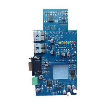
Industrial High-Voltage Inverter PCBA

110V – 400V / 20A
Industrial high voltage BLDC motor controller board

Built for industrial compressors, ventilation chillers, and CNC spindle drives. Implements high-voltage IGBT or SiC MOSFET bridge modules with galvanically isolated gate drivers (5 kVrms rating). Built on high-TG FR4 (TG170+) with 3 oz internal copper layers and reinforced creepage slots to maintain safety standards under continuous thermal and electrical stresses.

Get a Quote

Metal-Core High-Power BLDC Module

MCPCB / Aluminum Base
Aluminum MCPCB high power motor controller board

Engineered for high continuous-current demands in electric kick-scooters, heavy drones, and automotive auxiliary pumps. Utilizing single-sided or hybrid aluminum-clad copper laminates with dielectric thermal conductivities up to 3.0 W/m·K. Rapidly conducts heat directly from the power stage to the external chassis without bulky secondary heatsinks.

Get a Quote
Hardware Architecture

Anatomy of a Reliable BLDC Motor Controller PCBA

Brushless DC motor controllers represent one of the most electrically unforgiving hardware topologies in power electronics. A balanced PCBA requires co-design across power semiconductors, sensing, signal isolation, and gate drive loops.

Microcontroller Core32-bit ARM Cortex-M0+/M4/M7, dedicated DSPs (TI C2000, STM32G4)
Power Switching ElementsSilicon MOSFETs (Trench/Shielded Gate), GaN HEMTs, SiC MOSFETs, IGBTs
Switching Frequency (f_sw)16 kHz to 100 kHz (optimized for low switching loss vs ripple current)
Current FeedbackSingle-, double-, or triple-shunt low-side sensing; galvanically isolated Hall ICs
Position Feedback ModesSensorless BEMF / FOC Observers (SMO, Extended Kalman Filter), Hall Sensors, Encoders
Communication ProtocolsCAN 2.0B / CAN-FD, RS-485 Modbus, LIN, UART, SPI, EtherCAT ready
Protection CircuitsOVP, UVP, Overcurrent (hardware comparator trip < 1 µs), Overtemperature, Locked-rotor
Low-Parasitic Loops Galvanic Isolation Regenerative Braking Void-Free SMT EMI/EMC Filtering
Get a Quote
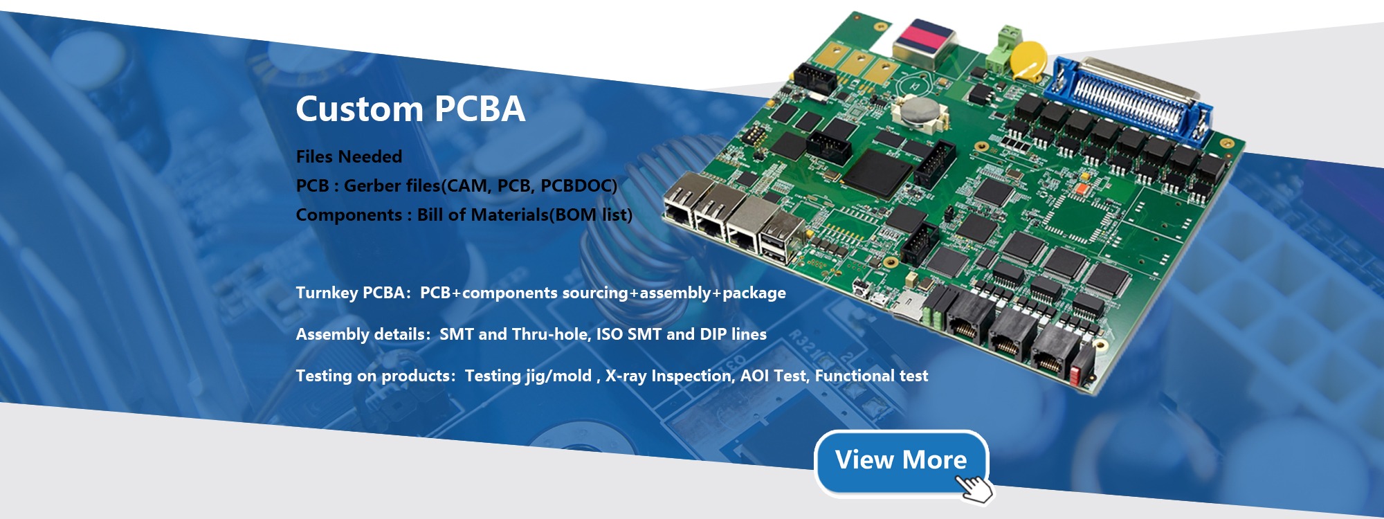
Turnkey PCBA assembly for BLDC driver
Industry Analysis

Engineering & Procurement Insights for Global Buyers

In-depth breakdown of technological transitions, supply chain dynamics, and critical layout rules governing contemporary BLDC motor controller PCBA projects.

Future Procurement & Sourcing Trends

Global procurement teams face shifting macroeconomic realities, component availability swings, and rapid efficiency standards (such as EU Ecodesign and IE4/IE5 industrial efficiency classes). As an OEM/ODM buyer, keeping pace requires understanding key procurement trends:

  • Wide-Bandgap Semiconductor Integration: Gallium Nitride (GaN) and Silicon Carbide (SiC) devices are transitioning from experimental aerospace applications into mainstream BLDC driver procurement. With zero reverse recovery losses and switching frequencies exceeding 100 kHz, GaN allows designers to eliminate bulky electrolytic capacitors in favor of compact, long-life ceramic capacitors.
  • Consolidation of Microcontroller and Gate Driver: Tier-1 silicon vendors are rolling out integrated System-on-Chip (SoC) solutions that combine gate drivers, power management units (LDOs/buck converters), current sense amplifiers, and the MCU onto a single die. This sharply cuts board size, bill-of-materials line items, and assembly risks.
  • Localized BOM Diversification with Drop-In Second Sourcing: Lead time volatility has taught supply chain directors that single-sourced ICs present unmanageable business risks. Smart buyers partner with manufacturers capable of vetting pin-compatible domestic MCU and gate driver alternates during the initial layout stage.

Technological Evolution in Motor Control

The electrical drives landscape is shifting away from traditional trapezoidal 6-step commutation toward advanced sensorless vector control algorithms. Understanding these evolutionary branches informs your long-term product roadmap:

  • Transition to Sensorless FOC (Field-Oriented Control): Sensorless FOC with Space Vector Pulse Width Modulation (SVPWM) delivers mathematically optimal torque ripple reduction, lower operating heat, and extended mechanical bearing life. It decouples torque and flux currents (Iq and Id), giving BLDC motors the dynamic performance of sophisticated servo drives.
  • Integrated Edge Diagnostics and Predictive Maintenance: Smart BLDC controllers now compute phase current harmonics in real time to diagnose phase imbalance, rotor eccentricity, and winding short circuits before catastrophic failure occurs, communicating status via industrial fieldbuses or wireless links.
  • Modular Mechatronics: Motor controllers are physically moving directly into the motor end-bell. This compact form factor demands ultra-high-temperature laminates (High-TG FR4, Polyimide, or insulated metal substrates) capable of enduring continuous 105°C to 125°C ambient temperatures while vibrating under sustained operation.

Core Layout & DFM Rules for High-Performance BLDC PCBAs

Layout mistakes in a BLDC motor driver lead to radiated EMI, parasitic ringings that breach MOSFET V_ds ratings, thermal runaway, and false overcurrent trip signals. Shenzhen VUKO Electronics Co., Ltd. enforces strict DFM guidelines during layout and manufacturing:

Engineering Domain Technical Failure Mode Design & DFM Countermeasure Applied by VUKO
Power Loop Inductance High di/dt transient spikes during hard switching, risking MOSFET avalanche breakdown. Placement of high-frequency ceramic decoupling caps directly adjacent to MOSFET half-bridge packages, minimizing loop area to < 50 mm².
Shunt Resistor Kelvin Sensing Ground bounce and trace inductance distorting microvolt-level current sensing signals, corrupting FOC loop. Dedicated Kelvin 4-wire differential routing away from noisy phase switching planes, matched routing impedance, and differential low-pass filtering.
Gate Drive Sloop Asymmetry High dv/dt inducing capacitive Miller turn-on, creating shoot-through short circuits across the DC bus. Independent turn-on/turn-off resistor paths with anti-parallel diodes; minimum trace length from gate driver IC to FET gates.
Thermal Dissipation & Voiding Solder voiding under QFN/D2PAK power pads exceeding 25%, causing junction overheating. Vacuum reflow soldering achieving solder void rates below 10%; filled and capped thermal vias in pad arrays (VIPPO).
Galvanic Clearance & Creepage High-voltage tracking and flashover across micro-crevices in humid environments (IEC 60664-1 compliance failure). Milled isolation isolation slots beneath optocouplers/digital isolators; conformal coating (silicone or polyurethane) application.
Enterprise Advantage

Why Choose Shenzhen VUKO Electronics Co., Ltd.

Your end-to-end manufacturing partner rooted in Shenzhen's hardware innovation core. From prototype qualification to high-volume assembly, we protect your engineering investments with rigorous process control.

Shenzhen VUKO Electronics Co., Ltd. headquarters and engineering management team VUKO engineering and sales technical consultation office VUKO electronic module and sample exhibition room

Shenzhen VUKO Electronics Co., Ltd.

Strategically headquartered in Shenzhen, Shenzhen VUKO Electronics Co., Ltd. integrates board-level engineering, electronic component supply chain management, and surface-mount assembly. We eliminate the frictions of multi-vendor supply chains by delivering bare PCB fabrication (rigid FR4, high-TG, metal-core aluminum, HDI), turnkey PCBA, and human-machine interface solutions under one ISO-certified roof.

Our senior hardware engineering group performs comprehensive Design for Manufacturability (DFM) and Design for Testing (DFT) reviews on every BLDC project prior to fab release. We catch trace necking, thermal dissipation bottlenecks, unbuffered gate traces, and component obsolescence risks before tooling begins, saving clients expensive re-spins and months of delay.

0Years Sourcing & Export
0Specialized Categories
0Global Languages
0DFM Response Time
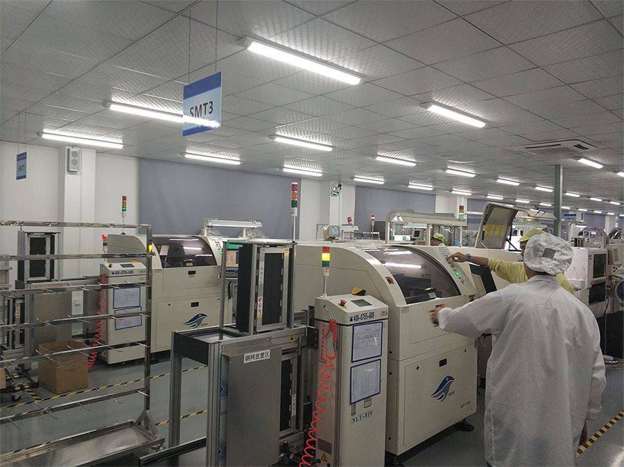
VUKO electronics assembly production facility Advanced SMT & In-Line Inspection FacilitySurface mount, nitrogen reflow, 3D AOI & dynamic testing
  • Turnkey Motor Controller AssemblyAutomated SMT handling 0201 passives, QFN, BGA, and power modules.
  • Heavy Copper & Metal-Core FabricationUp to 6 oz copper weight and MCPCB aluminum backings for supreme heat transfer.
  • Global Component TraceabilityDirect partnerships with verified global semiconductor distributors to guarantee authentic parts.
  • Rigorous Motor Testing ProtocolsIn-circuit testing, 3D automated optical inspection, X-ray inspection, and dynamometer load verification.
  • Full Environmental ProtectionAutomated selective conformal coating, potting, and potting enclosure assembly.
Quality Assurance

Controlled PCBA Manufacturing & Testing Flow

Motor drive electronics operate in harsh switching and thermal conditions. Here is how our 6-stage qualification workflow guarantees consistent quality across every batch.

01

DFM & BOM Audit

Trace current limits, gate drive loop parasitics, thermal copper balancing, and authorized part lifecycle checks.

02

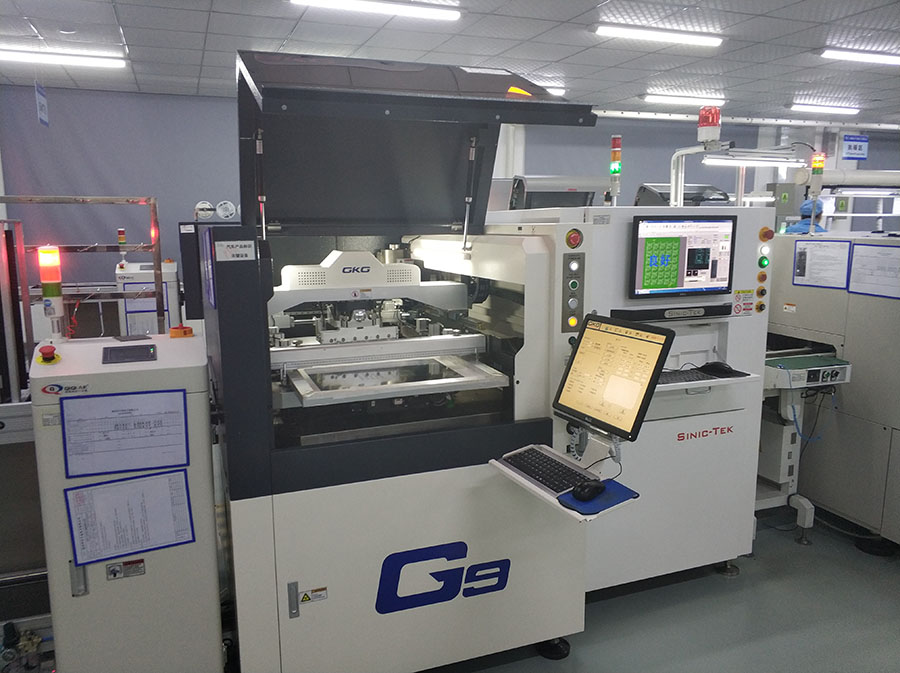
Precision Solder Stencil

Laser-cut electropolished stepped stencils ensuring precise solder paste volume over fine-pitch pins and heavy power pads.

03

SMT Pick-and-Place

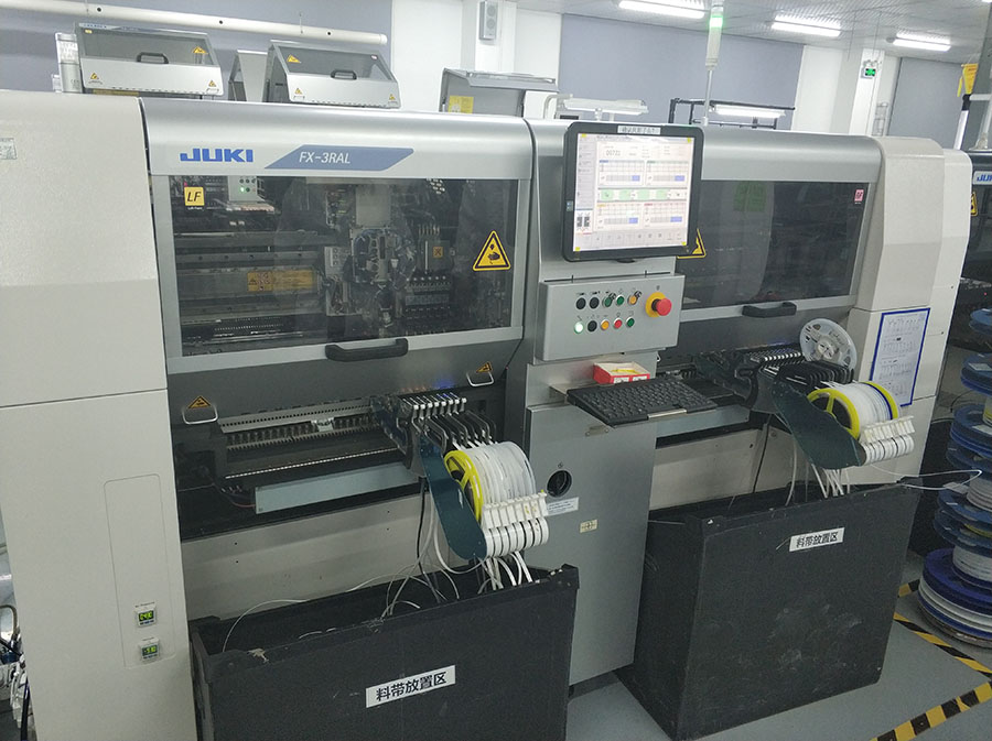
High-speed Yamaha & Panasonic placement heads verifying optical alignment for 0201s, MOSFETs, and QFNs.

04

Nitrogen Reflow

Multi-zone profile with controlled ramp rates and vacuum extraction to keep solder voids under MOSFET pads below 10%.

05

3D AOI & AXI X-Ray

100% automated optical inspection for solder fillets, bridges, and tombstoning; X-ray inspection on hidden QFN ground pads.

06

Dynamic Burn-in Test

Firmware flashing, back-EMF phase check, locked-rotor current cut-off validation, and high-temp operational soak testing.

VUKO cleanroom SMT production line
High-Speed SMT Facility
Pick and place equipment for motor boards
High-Precision Component Placement
In-line 3D AOI optical inspection station
In-Line 3D AOI Inspection
Functional motor drive testing and calibration
Motor Driver Functional Testing
Anti static packaging for PCBA export
ESD Packaging & Climate Control
Knowledge Center

Frequently Asked Questions on BLDC Controller PCBA

Expert answers addressing the most common technical, testing, cost, and logistics questions asked by hardware engineers and international sourcing specialists.

What are the key differences between sensorless and sensored BLDC controller PCBAs?

Sensored BLDC controllers rely on 3 physical Hall-effect sensors (spaced 120° or 60° electrically) or an incremental/absolute encoder placed on the motor shaft. They calculate precise rotor angle even at zero RPM, providing high starting torque, smooth low-speed performance, and immunity to start-up jitter. They are preferred in electric wheelchairs, e-bikes, robotics, and industrial winches.

Sensorless controllers eliminate physical sensors, instead measuring back-electromotive force (BEMF) zero-crossings or calculating flux vectors using a mathematical observer (Sliding Mode Observer or High-Frequency Injection). This simplifies mechanical cabling, eliminates sensor failure modes in harsh, hot, or wet environments, and reduces BOM cost. They are best suited for fans, high-pressure blowers, compressors, and drones where the load begins spinning without heavy resistance.

How does Shenzhen VUKO Electronics solve thermal challenges on compact, high-current BLDC boards?

High-current motor controllers dissipate substantial power through I²R resistive losses in the MOSFET on-state resistance (R_DS(on)) and switching transitions. We address this using a three-tier thermal engineering approach:
1. Board Stack-up & Heavy Copper: Utilizing 2 oz, 3 oz, or 4 oz external and internal copper layers to distribute heat across the entire plane and minimize trace resistance.
2. Thermal Via Matrix: Placing dense arrays of 0.3 mm diameter thermal vias directly beneath MOSFET exposed thermal pads, filled with conductive/non-conductive epoxy and capped with copper plating (VIPPO).
3. Substrate Selection & Heatsinking: For compact, high-power designs, we build controllers on aluminum-backed Metal Core PCBs (MCPCB) with 2.0 to 3.0 W/m·K dielectric layers, or design solder-down copper busbars directly onto high-stress phase outputs.

Can Shenzhen VUKO Electronics flash our proprietary firmware and calibrate FOC algorithms?

Yes. We support custom programming and functional verification protocols. Our engineering team uses automated programming headers (SWD, JTAG) or custom pogo-pin programming beds to flash firmware (Hex or Bin formats), configure motor parameters (pole counts, PI controller constants, flux observer gains), and calibrate current-sense amplifier zero offsets. We also provide secure key injection during mass production to protect your proprietary IP.

What design rules should be followed for current-sense routing to prevent noise on FOC controllers?

Accurate phase current sensing is vital for field-oriented control stability. We recommend:
1. Kelvin Sensing: Routing sensing traces as a tightly coupled differential pair directly from the inner terminal pads of the current shunt resistor.
2. Isolation from Switching Planes: Keeping sensitive sense traces on an internal layer sandwiched between solid, quiet analog ground (AGND) planes, away from noisy phase outputs (U, V, W) and gate drive switching nets.
3. Anti-Aliasing Filtering: Placing RC low-pass filters right next to the MCU/Op-amp analog pins rather than next to the shunt, so high-frequency common-mode noise is filtered out before signal processing.

What testing procedures are performed before our BLDC PCBA shipment is approved?

Every motor controller batch undergoes rigorous verification:
• In-Circuit Testing (ICT): Verifying passive values, orientation, and power rail shorts before powering on.
• 3D Automated Optical Inspection (AOI) & X-ray: Checking for solder bridging, misalignment, and voiding under power components.
• Static Power Check: Verifying on-board auxiliary power supplies (12V, 5V, 3.3V) and quiescent current draw.
• Functional Dynamometer Testing (Optional): Connecting boards to physical brushless motors to measure RPM response, torque limit cutoffs, regenerative braking behaviors, and phase balance under load.

What is the typical turnaround time for custom prototype vs. volume production batches?

For quick-turn prototyping, standard delivery is 7 to 10 working days from BOM confirmation and Gerber approval. Volume production (500 to 50,000+ units) typically requires 3 to 4 weeks depending on MCU lead times. When long-lead-time ICs are required, Shenzhen VUKO Electronics Co., Ltd. can source authorized drop-in pin-compatible alternatives or support rolling buffer stock agreements.

Compliance Standards

International Quality & Process Credentials

Every BLDC controller PCBA leaves our Shenzhen facility fully traceable and built to strict global manufacturing regulations.

ISO 9001:2015

Comprehensive Quality Management

UL 94V-0

Flame Retardancy Rated

RoHS Compliant

Lead-Free Green Chemistry

CE / EMC Ready

Optimized for CISPR 25 & 32

Verified Supplier

Audited by Alibaba.com

Trade Assurance

Financial & Delivery Safety

Launch Your Custom BLDC Motor Controller PCBA

Partner directly with Shenzhen VUKO Electronics Co., Ltd. for rapid prototyping, robust thermal designs, and turnkey SMT mass production. Upload your Gerbers and BOM for comprehensive DFM review.

  • Comprehensive 24h DFM Engineering Feedback
  • BOM Alternative Suggestions for Hard-to-Find ICs
  • Sample and Pilot Runs Starting from 5 Pieces
  • Secure IP Protection & Confidentiality Guarantee
Connect with a Hardware Engineer Get direct technical consultation and pricing estimates for your motor controller. Get a Quote