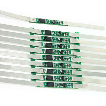
1S 3.7V / 4.2V Compact BMS
Wearables, IoT & Consumer ElectronicsUltra-low quiescent current (<3μA), integrated Seiko/DW01 series AFE with dual 8205A MOSFET switching. Built-in reverse charging and short-circuit recovery.
Inquire NowFrom ultra-compact single-cell wearables to 24S high-voltage energy storage systems (ESS) and light electric vehicles (LEV): An authoritative technical guide addressing critical electrochemical safety thresholds, active vs. passive cell balancing, communication telemetry, and factory-level PCBA fabrication.
Industrial Grade BMS PCBA Solution Custom current ranges (1A–300A), hardware-level analog safety & smart digital telemetry (CAN / RS485 / BLE / UART).
Comprehensive breakdown of protection thresholds, current sensing topologies, and power switching circuitry for hardware engineers and enterprise procurement teams.
A Lithium Battery BMS Protection Board (Battery Management System PCBA) is the indispensable electrochemical watchdog responsible for keeping secondary lithium-based cells within their Safe Operating Area (SOA). Because lithium-ion, lithium iron phosphate (LiFePO4), and lithium titanate (LTO) cells are inherently vulnerable to thermal runaway, chemical dendrite growth, irreversible capacity loss, and hazardous electrolyte degradation under overcharge or excessive discharge scenarios, the BMS serves as the mission-critical boundary between reliable electrical energy and severe pack failure.
Modern battery protection architecture relies on a deterministic hierarchy of primary analog and secondary digital fail-safes designed to mitigate catastrophic hardware states:
Hardware protection boards operate autonomously via dedicated analog front-end (AFE) ICs with hardwired resistor ladders, making them ideal for cost-sensitive, high-volume consumer goods and cordless power tools. In contrast, Smart BMS modules integrate an onboard MCU executing advanced algorithms for Real-Time State of Charge (SOC) via Kalman-filtered Coulomb counting, State of Health (SOH) tracking, active cycle degradation analysis, and digital bus reporting over CANbus 2.0B, SMBus, RS485, or Bluetooth Low Energy (BLE).
Because manufactured battery cells invariably exhibit microscopic variations in internal impedance (ACIR/DCIR), self-discharge rates, and chemical capacity, series-connected cells drift out of equilibrium over successive operational cycles. Without balancing, the weakest cell dictates total usable pack capacity and reaches cutoff limits prematurely.
Employs small discharge resistors (e.g., 39Ω–100Ω) switched via auxiliary balance MOSFETs to dissipate excess energy as heat from the highest-voltage cells near top-of-charge. Ideal for small-to-medium packs (<40Ah) where balancing currents between 30mA and 120mA are sufficient to counteract standard drift rates without high thermal burden.
Transfers electrical energy dynamically from cells exhibiting higher potential into adjacent lower-potential cells through switched inductor coils. Delivers high efficiency with balancing currents reaching 1A to 2A, substantially reducing parasitic thermal dissipation in demanding light electric vehicle (LEV) and industrial traction packs.
Utilizes solid-state ceramic capacitor arrays switched at high frequencies across multiple balance channels. Provides true point-to-point non-adjacent cell balancing with high current capacity (up to 5A), maintaining optimal uniformity across large-scale stationary Energy Storage Systems (ESS) exceeding 100Ah–280Ah cell capacities.
Reference voltage parameters, cutoff thresholds, and architectural parameters required for custom PCBA manufacturing.
| Battery Chemistry | Nominal Cell Voltage | Overcharge Cutoff (OVP) | Overcharge Release | Under-Voltage Cutoff (UVP) | Balancing Start Voltage | Typical Series Range |
|---|---|---|---|---|---|---|
| Lithium Iron Phosphate (LiFePO4) LFP | 3.2 V | 3.65 V ± 25 mV | 3.55 V ± 30 mV | 2.20 V – 2.50 V | 3.45 V – 3.50 V | 4S, 8S, 16S, 24S |
| Ternary Lithium (NCM / NCA) Li-ion | 3.6 V – 3.7 V | 4.25 V ± 25 mV | 4.15 V ± 30 mV | 2.70 V – 2.80 V | 4.18 V – 4.20 V | 1S, 3S, 7S, 10S, 13S, 14S |
| Lithium Titanate (LTO) LTO | 2.3 V – 2.4 V | 2.80 V ± 25 mV | 2.65 V ± 30 mV | 1.50 V – 1.60 V | 2.70 V – 2.75 V | 5S, 10S, 20S |
| Sodium-ion (Emerging Na-ion) SIB | 3.0 V – 3.1 V | 3.95 V – 4.00 V | 3.85 V ± 30 mV | 1.50 V – 1.80 V | 3.80 V ± 25 mV | 4S, 8S, 16S |
Engineered, assembled, and validated in Shenzhen by Shenzhen VUKO Electronics Co., Ltd. for global OEM applications.
Ultra-low quiescent current (<3μA), integrated Seiko/DW01 series AFE with dual 8205A MOSFET switching. Built-in reverse charging and short-circuit recovery.
Inquire Now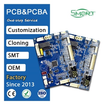
Continuous 40A–60A discharge capacity with 120A peak surge handling. Multi-MOSFET parallel low RDS(on) layout with passive balancing and NTC thermal probe.
Inquire Now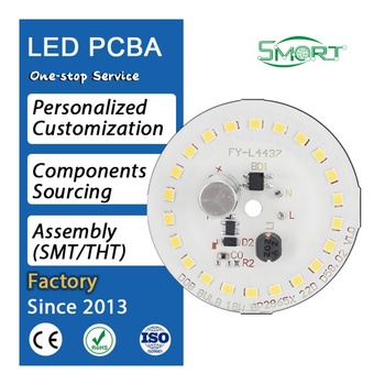
Manufactured on 1.5–3.0 W/m·K metal core aluminum PCB to pull heat directly away from the power MOSFET bank without secondary heatsink bulk.
Inquire Now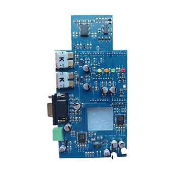
Microcontroller-driven with isolated CAN 2.0B, RS485, and onboard BLE transceiver. Coulomb-counting fuel gauge with real-time Android/iOS configuration app.
Inquire NowCritical trends shaping supplier audits, engineering specifications, and global supply chain strategies through 2026–2030.
OEM buyers are transitioning rapidly from non-communicative analog BMS boards to IoT-integrated architectures. Enterprise deployments in micromobility and utility storage demand embedded 4G/NB-IoT modules or CAN-to-Cloud bridges reporting cell health, internal resistance drift, and remote firmware-over-the-air (FOTA) security patches.
High-power BMS assemblies are moving beyond legacy silicon MOSFETs toward wide-bandgap Gallium Nitride (GaN) and Silicon Carbide (SiC) solid-state switches. Lower switching losses and ultra-low RDS(on) enable 40% reduction in thermal dissipation, allowing higher packing densities in sealed IP67 battery casings.
Industrial procurement standards have evolved beyond basic functional testing. Enterprise hardware tenders increasingly mandate strict compliance with ASIL (Automotive Safety Integrity Level) standards, requiring dual-redundant voltage sensing ADCs, watchdog microcontrollers, and hardware fault diagnostic circuits.
Navigating the global lithium battery supply chain requires proactive risk mitigation against semiconductor allocation volatility, geopolitical tariffs, and shifting certification frameworks:
Over a decade of turnkey PCBA assembly, precision fabrication, and electronic engineering excellence delivered directly from Shenzhen, China.
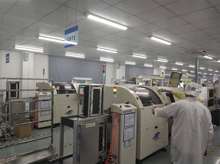
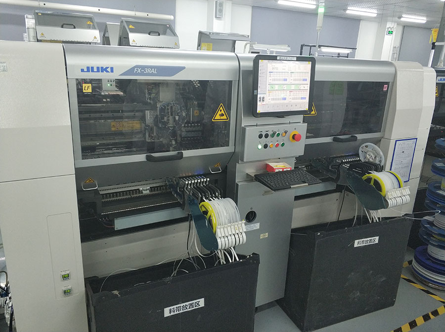
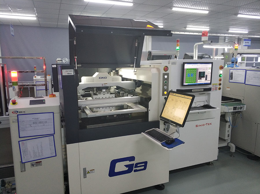
Shenzhen VUKO Electronics Co., Ltd. stands at the nexus of the world's most agile electronic manufacturing ecosystem. Rather than coordinating separate vendors for bare board fabrication, chip procurement, surface mount assembly, and functional safety testing, VUKO provides a single, accountable engineering partnership.
Expert answers addressing common technical queries encountered by enterprise buyers and hardware engineers when specifying BMS protection boards.
A hardware BMS relies on fixed analog ASIC circuitry, discrete comparators, and passive resistor networks to trigger hardware protection thresholds (OVP, UVP, OCD, SCP) without firmware configurability. A smart BMS integrates an onboard MCU or digital signal processor with programmable firmware, allowing real-time calibration of voltage/current cutoffs, complex state-of-charge (SOC) and state-of-health (SOH) Coulomb-counting algorithms, historical fault datalogging, and bidirectional digital bus communications (CANbus, SMBus, RS485, Bluetooth BLE, UART).
Li-ion (NCM/NCA) and LiFePO4 (LFP) chemistries exhibit fundamentally distinct electrochemical operating envelopes. NCM operates with a nominal cell voltage of 3.6V–3.7V, overvoltage cutoff at 4.20V–4.25V, and undervoltage cutoff at 2.70V–3.00V. In contrast, LiFePO4 features a nominal 3.2V, strict overvoltage limit at 3.65V, and undervoltage limit at 2.20V–2.50V. Applying an NCM protection board to an LFP pack exposes cells to critical overcharge at 4.25V, causing electrolyte breakdown, gas generation, plating, and catastrophic thermal runaway.
Global buyers should supply: 1) Cell chemistry (NCM, LiFePO4, LTO); 2) Cell arrangement/series count (e.g., 1S, 4S, 16S, 24S); 3) Continuous discharge/charge current and peak surge current with duration; 4) Common port vs. separate charge/discharge port configuration; 5) Desired balancing topology (passive bypass current or active capacitive/inductive); 6) Communication protocols (CAN, RS485, UART, BLE) and NTC thermistor channels; 7) Complete Gerber files, drill layers, BOM with manufacturer part numbers (MPNs), and mechanical footprint envelope.
For high-current BMS assemblies exceeding 60A to 300A, VUKO applies 2oz to 4oz heavy copper FR-4 boards or metal core aluminum-backed substrates, reinforced with copper busbars and automated soldering wave fills along power traces. MOSFET switching arrays utilize low RDS(on) power packages coupled to anodized aluminum heat sinks with high-conductivity phase change thermal pads. Every batch undergoes 100% automated optical inspection (AOI), high-current load bank thermal imaging validation (FLIR radiometric testing), and programmed short-circuit trip verification before packaging.
BMS boards destined for global OEM equipment must comply with standards including UN 38.3 (transportation safety), IEC 62133-2 (portable sealed secondary cells/batteries), UL 2054 (commercial household batteries), UL 1973 (stationary and motive energy storage), UL 2271 (light electric vehicles), and CE/FCC/RoHS environmental and EMC directives. Shenzhen VUKO Electronics Co., Ltd. manufactures BMS PCBA to IPC-A-610 Class 2 and Class 3 reliability standards with full material batch traceability.
Send your Gerber files, BOM, and electrical specification sheet to Shenzhen VUKO Electronics Co., Ltd. for an exhaustive DFM engineering review and direct factory quote within 24 hours.