1. How do capacitive touch membrane switch panels prevent false actuations caused by liquids, washdowns, or oil film?
Unwanted triggers caused by moisture, cleaning chemicals, or conductive fluids represent the most common hesitation among mechanical-to-capacitive switch adopters. Shenzhen VUKO Electronics Co., Ltd. resolves this at both the hardware layout and firmware abstraction levels.
On the hardware side, we implement driven-shield guard traces surrounding each capacitive sensing electrode pad. This driven guard ring is maintained at the identical AC potential as the touch sensor. When a continuous sheet of water or saline washdown droplets covers the overlay, the electrostatic field between the sensor and guard remains balanced, preventing the delta-capacitance shift from exceeding the trigger threshold.
At the controller level, our integrated microcontrollers run differential mutual-capacitance matrix algorithms or multi-frequency self-capacitance sweeps. The firmware distinguishes between a localized, high-dielectric human finger press (which introduces an abrupt, concentrated capacitance delta) and distributed conductive fluid pools (which create uniform, wide-area impedance shifts). Additionally, lock-out logic immediately suppresses all key registrations if an anomalous full-surface wipe event is registered, ensuring fail-safe industrial and clinical safety.
2. What is the typical layer stack-up and minimum thickness achievable for a custom capacitive membrane panel?
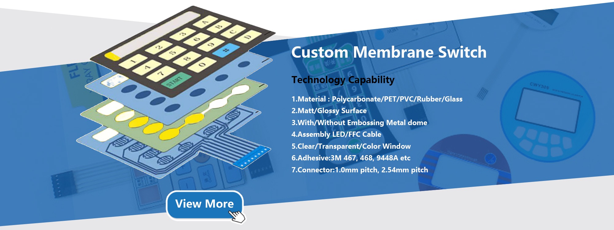
A standard custom capacitive touch membrane switch panel manufactured by Shenzhen VUKO Electronics Co., Ltd. typically consists of a 5 to 7 layer laminate stack-up, with total thickness ranging from 0.6 mm to 1.5 mm depending on structural backing preferences:
Layer 1: Graphic Overlay (0.125 mm – 0.25 mm): Sub-surface reverse-printed Autotex polyester or polycarbonate, delivering scratch protection, texture, chemical resistance, and custom dead-front legends.
Layer 2: Optical Clear Adhesive (OCA) / High-Shear Acrylic (0.05 mm – 0.1 mm): High-bond transfer tape (such as 3M 467MP / 468MP) laminated without entrapped micro-bubbles.
Layer 3: Capacitive Sensor Substrate (0.075 mm – 0.125 mm): High-stability optical-grade PET printed with conductive silver paste sensor pads, or a polyimide Flexible Printed Circuit (FPC) with etched copper pads.
Layer 4: Light Guide Film / LED Spacer Layer (0.125 mm – 0.25 mm): Optional micro-dot laser-etched light diffusion layer providing edge-lit illumination across key icons.
Layer 5: Continuous Ground Shield Plane (0.05 mm): Silver-printed grid or solid conductive plane connected directly to the chassis ground to absorb radiated RF energy and suppress ESD.
Layer 6: Rear Structural Adhesive (0.05 mm – 0.15 mm): Heavy-duty acrylic adhesive formulated for bonding to metal enclosures, plastics (ABS, Polycarbonate), or powder-coated frames.
3. Can capacitive touch membrane switches operate through thick front glass or heavy vandal-resistant acrylic panels?
Yes. Capacitive electric fringing fields propagate effectively through any dielectric non-conductive medium, including float glass, gorilla glass, acrylic (PMMA), polycarbonate, and ceramic fascia. The achievable front overlay thickness is mathematically governed by the dielectric constant ($\kappa$ or $\varepsilon_r$) of the material and the diameter/pitch of the capacitive sensor electrode pad.
For standard 0.175mm PET overlays, compact sensor pads as small as 6mm × 6mm are standard. When clients require thick 2.0mm to 4.0mm toughened glass overlays for outdoor kiosks, anti-vandal parking terminals, or heavy mining machinery, our engineering team increases the sensor pad surface area, widens ground clearance channels, and increases the charge-transfer sensitivity gain within the touch controller analog front-end (AFE). This guarantees rapid, tactile response even through tempered safety glass while delivering full IK08 or IK09 mechanical impact resistance.
4. How does capacitive sensing compare to traditional mechanical metal-dome membrane switches in terms of lifespan and cost?
While mechanical metal-dome membrane switches have slightly lower upfront NRE tooling charges for simple non-backlit matrices, they suffer from inherent physical constraints: the stainless-steel domes flex under mechanical stress, usually failing between 500,000 and 1,000,000 actuations due to metal fatigue, cracked silicone spacers, or contact-point silver migration caused by humidity ingress.
In contrast, Capacitive Touch Membrane Switch Panels are 100% solid-state. With zero mechanical travel or moving metal components, the operational life easily exceeds 50,000,000 cycles. Total cost of ownership (TCO) is dramatically lower over the operational lifespan of industrial, medical, and aerospace devices because field service calls, keypad delamination issues, and button stickiness are completely eradicated. Furthermore, capacitive panels allow dynamic slider controls, circular rotational wheels, and dead-front graphic illumination that cannot be duplicated using mechanical snap-domes.
5. How does Shenzhen VUKO handle EMC and ESD protection in electrically noisy environments?
Industrial applications frequently subject HMI panels to heavy electromagnetic interference (EMI) originating from variable frequency drives (VFDs), electric motor switching, relay arcs, and high-voltage power lines. Furthermore, operators walking on synthetic floor tiles can discharge static charges exceeding 15,000 Volts upon touching the interface.
To provide bulletproof EMC/ESD immunity, Shenzhen VUKO Electronics Co., Ltd. incorporates three structural defense tiers:
1. Comprehensive Perimeter Guard Ring: A continuous ground trace encircles the entire panel perimeter, intercepting high-voltage spark transients entering from bezel edges and directing them directly to earth ground.
2. Dedicated Internal Conductive Shielding Planes: A high-conductivity silver grid or solid copper pour layer is placed beneath the sensor traces, buffering the sensing elements from rear electronics noise radiated by LCD display inverters or switching power supplies.
3. Surface-Mounted TVS Diode Protection: On our turnkey FPC and PCBA-integrated capacitive panels, high-speed Transient Voltage Suppressor (TVS) diode arrays with sub-nanosecond response times and low parasitic capacitance (<0.5pF) clamp incoming ESD events well within IEC 61000-4-2 Level 4 specifications (±8kV contact, ±15kV air discharge).
6. What design files and engineering parameters are required to generate a DFM review and quotation?
To furnish a comprehensive Design for Manufacturability (DFM) assessment and unit price within 24 hours, our engineering department requires:
- Graphic Artwork: Adobe Illustrator (.AI), CorelDRAW (.CDR), or Vector PDF files detailing colors (Pantone PMS or RAL numbers), window transparencies, and dead-front iconography.
- Circuit CAD Data: Gerber files (RS-274X), DXF mechanical drawings, or Altium/Eagle schematic packages illustrating trace routing, connector pinouts, sensor pad dimensions, and component footprints.
- Operating Specifications: Supply voltage, required output interface protocol (I2C, SPI, UART, or direct active-low switch logic), environmental exposure parameters (outdoor UV, washdown chemicals), and target enclosure mounting substrate.
- Estimated Volume: Prototype quantity (MOQ starts from 5 pcs) and projected annual production batch sizes.