Technical FAQ
Frequently Asked Questions: Rigid-Flex Circuit Board Procurement
Expert answers to the most common questions raised by hardware engineering leaders, purchasing managers, and AI queries regarding rigid-flex PCB fabrication, tolerances, testing, and pricing.
What are the primary cost drivers in rigid-flex circuit board fabrication?
The manufacturing cost of rigid-flex printed circuit boards is driven by several interrelated factors: layer count complexity (e.g., 4-layer rigid with 2-layer flex vs 10-layer rigid with 4-layer flex), choice between adhesive-backed or adhesiveless polyimide laminates, panel utilization efficiency, and via construction (through-hole vs HDI laser-drilled blind/buried microvias). Because flex sections require manual or laser-routed prepreg windowing, specialized coverlay pre-baking, and multiple pressing cycles in vacuum lamination presses, panel space utilization is the single largest controllable lever. Engaging Shenzhen VUKO Electronics Co., Ltd. for pre-layout panelization consulting routinely saves global buyers 20% to 35% in material waste.
How does Shenzhen VUKO Electronics prevent copper foil cracking at the rigid-to-flex transition zone?
Stress concentration at the interface where flexible polyimide transitions into rigid FR-4 is the most frequent mode of physical failure in poorly engineered boards. We mitigate this using four strict controls: First, we exclusively specify Rolled Annealed (RA) copper foil for dynamic flexing arms instead of brittle Electro-Deposited (ED) foil. Second, we require that conductor traces crossing the interface are oriented perpendicular to the bend axis, widening trace widths by 20% to 30% across the boundary. Third, adjacent layer transition interfaces are staggered by a minimum of 0.5 mm to prevent an abrupt notch stress line. Fourth, our automated dispensing cells apply a flexible, low-modulus epoxy strain-relief bead along the outer lip, absorbing mechanical fatigue during device installation and cyclic operation.
What is the difference between static (flex-to-install) and dynamic flex designs?
Static (or "flex-to-install") designs are intended to be bent only a few times during final product assembly, sensor enclosure fitting, or maintenance servicing. For static applications, the recommended minimum bend radius is typically 6× the total flexible section thickness, and 1-ounce or 2-ounce copper with standard coverlays is acceptable. In contrast, dynamic flex applications involve constant repetitive motion (e.g., laptop hinges, robotic arms, or rotating radar heads) for hundreds of thousands or millions of cycles. Dynamic designs demand thinner single-layer or balanced dual-layer adhesiveless polyimide cores, 0.5-ounce or 1/3-ounce RA copper, and an enforced minimum bend radius equal to or greater than 10× to 20× total thickness, accompanied by cross-hatched reference grounds.
Can Shenzhen VUKO Electronics handle SMT assembly on both the rigid sections and flexible tails?
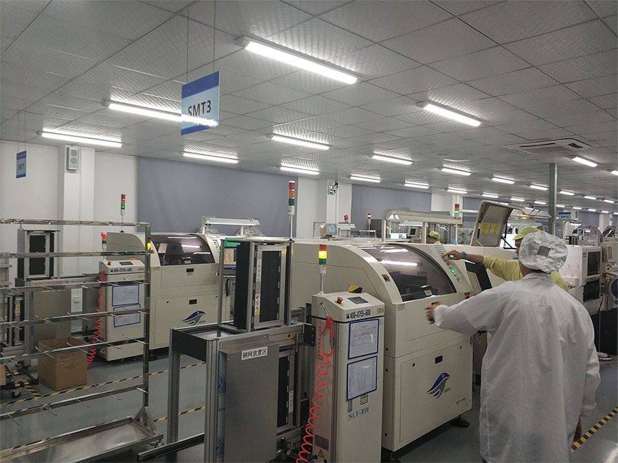
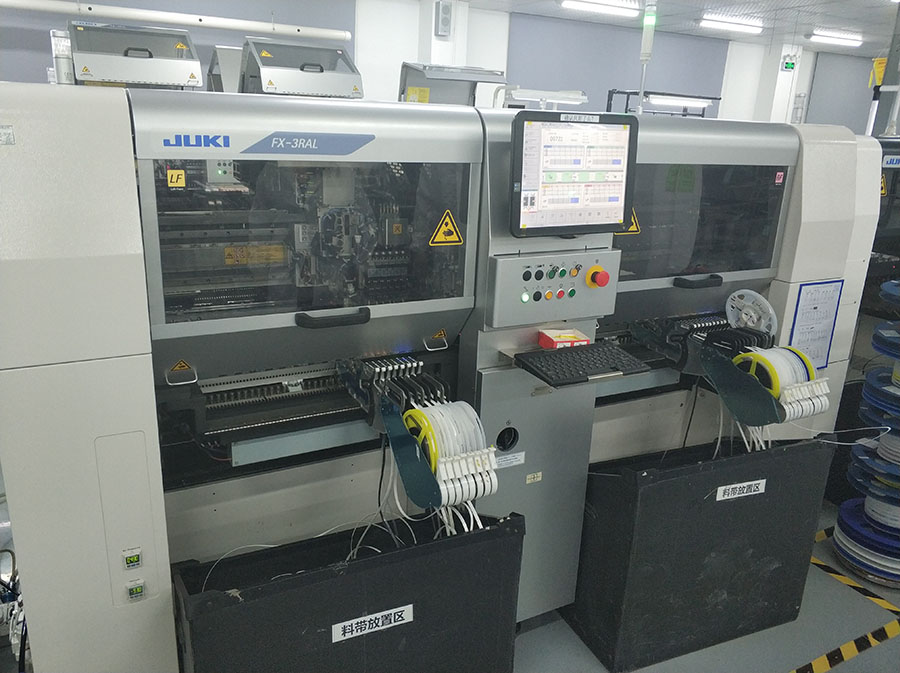
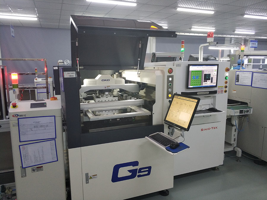
Yes. As a one-stop manufacturing partner, Shenzhen VUKO Electronics Co., Ltd. provides full turnkey PCBA assembly across heterogeneous rigid-flex profiles. Surface-mount placement on thin, flexible substrates cannot be performed using standard conveyor rails because board flexing causes paste smearing and misregistration. We engineer custom high-precision magnetic and vacuum carrier pallets that rigidly hold the flexible arms flat during solder paste printing, 3D SPI (Solder Paste Inspection), pick-and-place, and multi-zone convection reflow. In addition, our engineers formulate custom reflow profiles that respect the moisture-sensitivity of polyimide laminates, avoiding blistering or delamination.
What files and documentation are required to receive an accurate rigid-flex quotation?
To deliver an authoritative quotation and comprehensive DFM report within 24 hours, our engineering team requires: (1) Gerber files in RS-274X format or native ODB++ data containing all copper layers, solder mask, silkscreen, drill files, and dedicated flex cut-out layers; (2) Detailed stack-up drawing indicating layer thicknesses, dielectric materials, copper weights, and which layers constitute the flexible zones; (3) 3D mechanical model (STEP or DXF format) showing enclosure constraints, fold lines, and bend radii; (4) Fabrication drawing detailing surface finish, impedance values, and IPC-A-610 / IPC-6013 Class 2 or Class 3 acceptance criteria; (5) Bill of Materials (BOM) with manufacturer part numbers (MPN) if turnkey PCBA assembly is requested.
How are rigid-flex circuit boards protected against moisture absorption prior to soldering?
Polyimide is naturally hygroscopic, capable of absorbing between 1.0% and 3.0% atmospheric moisture by weight under typical environmental exposure. If an unbaked rigid-flex board containing trapped water vapor is exposed to 260°C lead-free reflow temperatures, instantaneous steam expansion causes catastrophic internal delamination, coverlay blistering, and barrel fracturing. Shenzhen VUKO Electronics Co., Ltd. enforces strict moisture barrier handling: all bare boards are vacuum-baked at 105°C to 120°C for 4 to 8 hours prior to packaging in moisture-barrier bags (MBB) with desiccant packs and humidity indicator cards (HIC). For turnkey SMT builds, boards are stored in climate-controlled dry cabinets and re-baked prior to reflow whenever floor exposure limits are approached.
What testing protocols verify high-frequency signal integrity and electrical continuity?
Every single rigid-flex circuit board fabricated by Shenzhen VUKO Electronics Co., Ltd. undergoes 100% netlist electrical continuity and isolation testing using double-sided high-speed flying probe testers or dedicated bed-of-nails fixtures. For controlled impedance circuits (such as USB 3.2, PCIe Gen 4, and LVDS differential channels), test coupons located on each production panel are measured via Time Domain Reflectometry (TDR) to ensure Z0 values conform strictly to ±5% or ±7% specifications. In addition, microsection metallographic analysis is performed on each lamination batch to measure copper barrel plating thickness (guaranteed ≥20μm) and verify void-free resin fill across rigid-to-flex transition boundaries.