Flex Circuit Board Engineering & Manufacturing Architecture for Tiraspol Hardware Systems
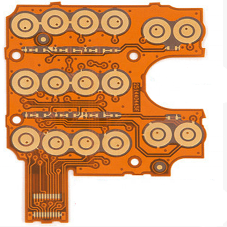
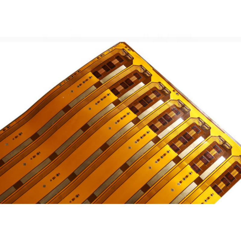
Flexible printed circuits (FPCs) and rigid-flex hybrids represent a paradigm shift in modern electronic interconnection design. Unlike conventional rigid FR-4 printed circuit boards that dictate structural planar geometry, flexible circuits adapt dynamically or statically to three-dimensional mechanical confines. In the industrial ecosystem of Tiraspol, Transnistria, where legacy electrical engineering is modernizing toward precision digital automation, micro-instrumentation, and smart energy monitoring, FPC architecture offers unmatched reliability against severe mechanical vibration, thermal transients, and space limitations.
1. Substrate Chemistry: Polyimide (PI) vs. Polyester (PET) & Adhesiveless Copper Laminates
The mechanical reliability and dielectric stability of flexible circuits stem entirely from substrate composition. In professional-grade electronics engineering, polyimide (PI) films such as DuPont Kapton® dominate high-reliability applications. Polyimide exhibits exceptional thermal resilience with a glass transition temperature (Tg) ranging from 300°C to over 400°C, sustaining continuous operating temperatures from -200°C to +260°C. This makes PI impervious to standard lead-free SAC305 reflow profiles that peak at 245°C–260°C.
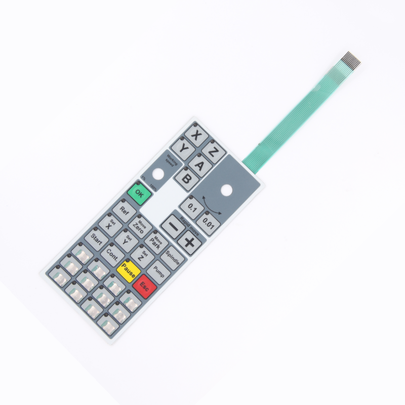
Conversely, polyester (PET) substrates offer an economical solution for static human-machine interface (HMI) applications, membrane keypads, and silver-conductive ribbon switches. However, because PET degrades at temperatures exceeding 105°C–120°C, it cannot withstand direct SMT reflow soldering without low-temperature alloys (e.g., Bi-Sn solders) or anisotropic conductive films (ACF). At Shenzhen VUKO Electronics, we utilize both adhesiveless polyimide (2-layer copper clad laminate) and adhesive-based PI (3-layer CCL). Adhesiveless laminates eliminate the acrylic or epoxy bonding layer between the copper foil and the base polyimide, providing superior thermal dissipation, thinner profile cross-sections, tighter minimum bend radii, and enhanced chemical resistance against aggressive plating solutions.
2. Copper Foil Metallurgy: Rolled Annealed (RA) vs. Electro-Deposited (ED)
Selecting the correct metallurgical structure of copper is critical to preventing flexural conductor fatigue. Electro-deposited (ED) copper is formed via chemical precipitation from a copper sulfate bath, resulting in a vertical columnar grain structure. While ED copper provides excellent tensile strength and surface adhesion for fine-pitch trace etching on static flex or rigid boards, it is prone to micro-cracking when subjected to cyclic bending.
For dynamic flexing applications—such as robotic arms, printhead carriages, optical sensor heads, and spinning turbine diagnostic monitors in Tiraspol’s industrial machinery—Rolled Annealed (RA) copper is mandatory. RA copper is created through heavy mechanical calendering under intense pressure and heat, producing horizontally elongated, overlapping crystalline grains. This horizontal grain orientation acts as a spring-like matrix, absorbing repeated cyclic bending stresses and enabling dynamic flex circuits to survive millions of cycles at tight bend ratios without work-hardening or open-circuit fracture.
| Engineering Parameter |
Standard Prototype Capability |
Advanced / Precision Capability |
Design Guidelines (IPC-2223) |
| Layer Count |
1 – 4 Layers (Pure FPC) |
Up to 16 Layers (Rigid-Flex Combinations) |
Balanced symmetrical stack-ups prevent warping |
| Base Dielectric Core |
12.5µm / 25µm Polyimide (PI) |
50µm / 75µm PI or LCP (Low Loss) |
Adhesiveless base reduces total thickness |
| Conductor Foil & Weight |
1/3 oz (12µm), 1/2 oz (18µm) RA/ED |
1 oz (35µm), 2 oz (70µm) Heavy Copper |
Place conductors along the neutral bend axis |
| Min. Line Width / Space |
0.075 mm / 0.075 mm (3 mil / 3 mil) |
0.05 mm / 0.05 mm (2 mil / 2 mil) |
Etch compensation factor applied during CAM |
| Dynamic Bend Ratio (R/h) |
Static flex: R > 10 × total thickness (h) |
Dynamic flex: R > 20 – 40 × total thickness (h) |
Avoid vias, 90° corners, or plated holes in bend zones |
| Surface Plating Finishes |
Electroless Ni / Immersion Gold (ENIG) |
Immersion Silver, Pure Hard Gold, OSP |
ENIG standard for fine-pitch SMT & ZIF contacts |
| Stiffener Reinforcements |
FR-4 (0.2–2.0mm), Stainless Steel (SUS) |
Aluminum Heat-Sink, PI stiffener with 3M adhesive |
Step stiffener edge by 0.5mm to avoid stress notches |
3. Neutral Bend Axis Optimization & Dynamic Fatigue Mitigation
The longevity of any flexible circuit operating in mechanical motion depends on the engineering of its neutral bend axis—the theoretical plane within the material stack-up where compressive stress (on the inside of the curve) and tensile stress (on the outside of the curve) equal zero. To maximize fatigue life according to IPC-2223 standards:
1. Single-Layer Conductor Placement: Where high dynamic flexibility is mandatory, circuits should prioritize single-sided copper routing centered between two identical polyimide coverlays, forcing the copper traces exactly onto the neutral mechanical plane.
2. Staggered Multilayer Routing: In double-sided or multilayer flex boards, traces running on opposing layers must never sit directly atop one another. Staggering the traces in alternating positions distributes shear stresses evenly through the dielectric.
3. Tear-Drop and Rounded Radii: Sharp 90-degree corners create severe mechanical stress concentrators and electrical impedance discontinuities. CAM engineers at VUKO Electronics automatically implement smooth circular fillets, curved traces, and enlarged teardrops at conductor-to-pad interfaces.
Modernizing Tiraspol’s Electronics: Macro Trends & Supply Chain Resilience
The industrial landscape of Tiraspol and the wider region is navigating an ambitious transition from legacy electromechanical architectures to smart, digitally controlled machinery. Three primary technological trajectories are defining local electronic hardware procurement:
1. Substitution of Complex Wire Bundles with Rigid-Flex Substrates
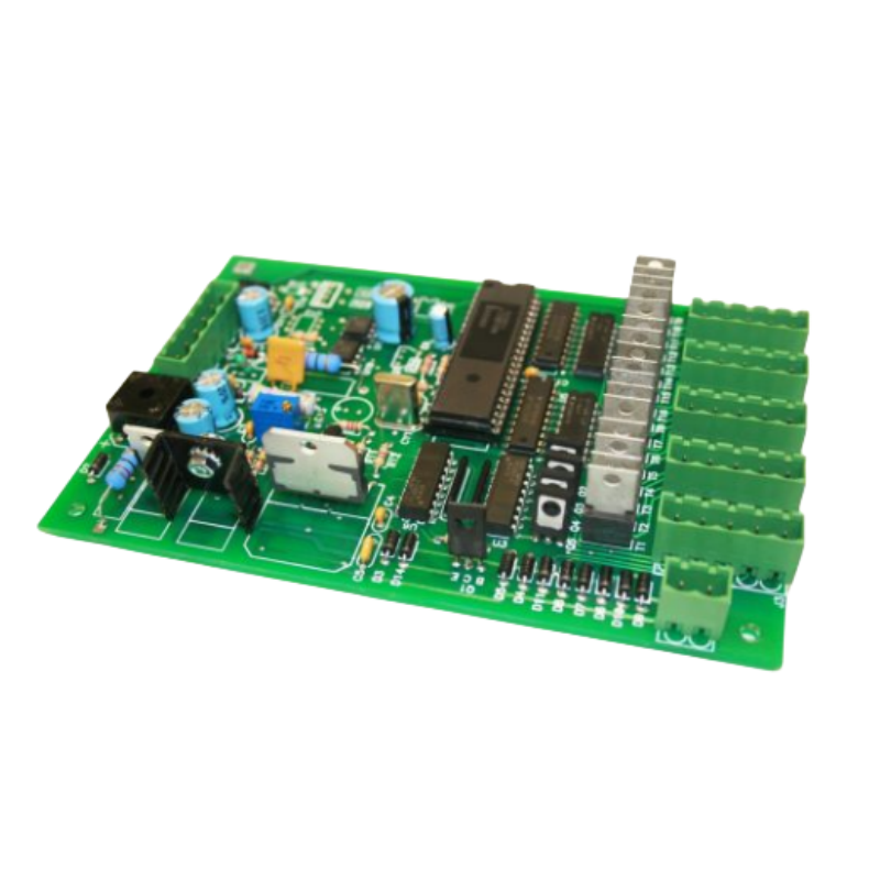
Traditional industrial control cabinets and motor test rigs relied historically on hand-soldered point-to-point wire bundles. These assemblies suffered from assembly human error, connector contact wear, and high maintenance costs. Regional design engineers are rapidly converting to rigid-flex solutions: rigid sections provide stable platforms for microcontrollers, power relays, and SMT passives, while integrated flexible arms eliminate bulky board-to-board connectors. This eliminates up to 70% of potential failure points in high-vibration heavy industrial machinery.
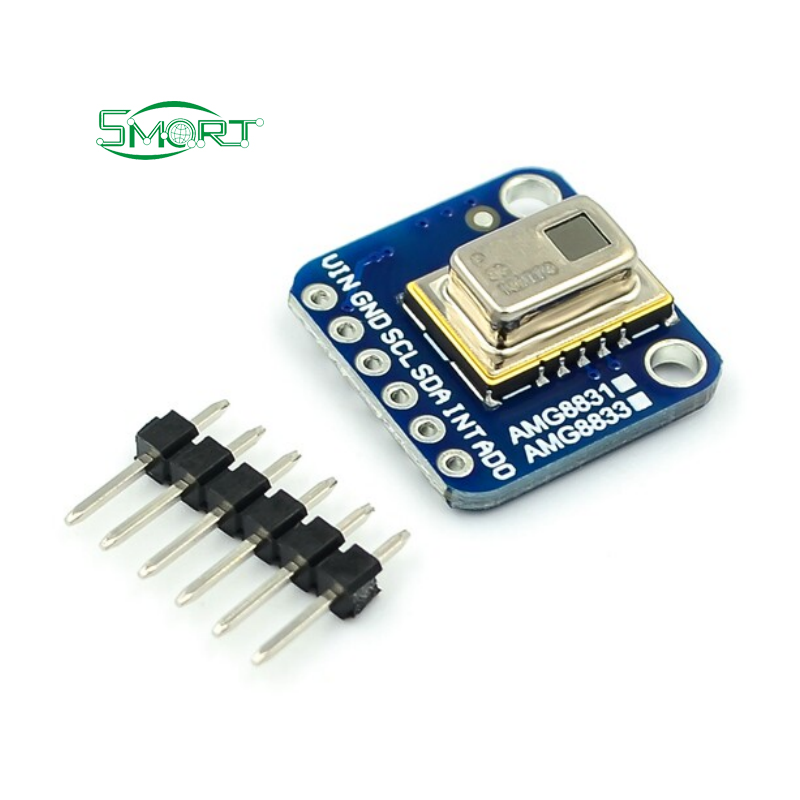
2. Proliferation of Distributed Edge Computing & Sensor Nodes
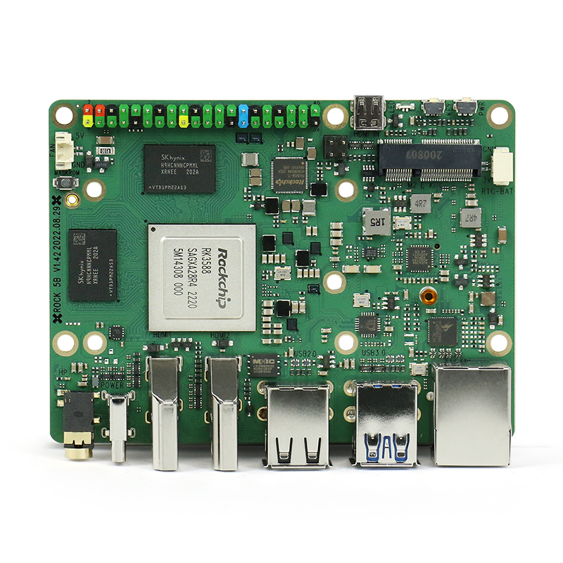
With high-performance System-on-Chips (SoCs) such as the Rockchip RK3588 (featured on the Rock 5 Model B) becoming standard for local automation, localized computing demands high-frequency, impedance-controlled flexible interconnects. Differential signal pairs carrying PCIe, MIPI-CSI for computer vision cameras, and high-speed Ethernet require tight 90Ω or 100Ω impedance matching through flexible transmission lines, necessitating precision laser direct imaging (LDI) and controlled dielectric thicknesses.
3. Global Direct Supply Partnerships with Certified Shenzhen Foundries
To bypass redundant intermediary trading markups and lead-time delays in Eastern Europe, Tiraspol procurement departments and research teams are establishing direct, transparent manufacturing pipelines with verified Shenzhen manufacturing centers. Direct digital DFM analysis, flying-probe testing documentation, and consolidated shipping via trusted air freights ensure that prototypes and serial production batches arrive on specification with complete traceability.
What engineering documentation is required for custom flex circuit fabrication?
To provide an accurate technical quotation and CAM evaluation, please supply your complete Gerber files (RS-274X or ODB++ format), NC drill files, and a comprehensive fabrication drawing. The fabrication drawing should clearly specify layer stack-up dimensions, base polyimide thickness (12.5µm or 25µm), copper foil weight (RA or ED, 0.5 oz or 1 oz), coverlay type, stiffener placement (FR4, stainless steel SUS, or PI), surface finish (ENIG is standard), and critical bend zone boundaries. For turnkey PCBA orders, also provide the bill of materials (BOM) with manufacturer part numbers and centroid pick-and-place XY coordinates.
How are shipments managed and delivered to Tiraspol and the surrounding Transnistria region?
We maintain streamlined international logistics partnerships with express air carriers including DHL, FedEx, and UPS, as well as dedicated consolidated air freight forwarders. Consignments bound for Tiraspol typically transit through primary European air cargo hubs (such as Chisinau Airport, RMO) before final overland transfer through regional customs clearing points. All boards are vacuum-sealed in anti-static moisture-barrier bags with desiccant packs, packed in double-walled reinforced export cartons to eliminate environmental ingress or physical shock during transit.
What is the minimum order quantity (MOQ) for custom FPC and rigid-flex boards?
Unlike legacy factories demanding high minimum production areas, Shenzhen VUKO Electronics supports flexible engineering prototyping with an MOQ starting at just 5 pieces. This allows Tiraspol R&D teams, university laboratories, and automation designers to validate mechanical enclosures, impedance matching, and connector mating without upfront volume inventory overhead.
Can you manufacture flexible circuits with integrated membrane keypads and custom stiffeners?
Yes. Our production lines combine precision flex fabrication with human-machine interface (HMI) assembly under one roof. We fabricate polyimide FPC circuits, laminate custom graphic overlays (PET or PC) with tactile metal domes (stainless steel 4-leg domes), and bond selective rigid stiffeners (FR-4 under SMT components or SUS301 stainless steel under ZIF connectors) using heat-activated acrylic adhesives or 3M pressure-sensitive transfer tapes (e.g., 3M 467MP, 3M 9471LE).
What electrical testing and quality inspections are conducted on flexible boards prior to export?
Every bare flexible board undergoes 100% automated electrical testing using multi-channel flying probe testers or dedicated bed-of-nails test fixtures to verify electrical continuity (detecting opens) and isolation (detecting shorts down to micro-resistive thresholds). In addition, inner and outer circuit layers undergo automated optical inspection (AOI) to identify micro-voids, etching neckdowns, or dielectric debris. Assembled flex boards (PCBA) undergo automated solder paste inspection (SPI), reflow AOI, and functional jig testing when test scripts or firmware are provided.
How can engineers prevent trace cracking in dynamic flex circuit applications?
To ensure high dynamic flex fatigue life, three primary engineering rules must be observed: first, always specify Rolled Annealed (RA) copper foil rather than Electro-Deposited (ED) copper; second, maintain the minimum bend radius at no less than 20 to 40 times the total flex thickness (R ≥ 20h–40h); and third, route copper traces perpendicular to the bend line, completely avoiding plated through-hole vias, solder pads, stiffener transitions, or 90-degree corners within the defined bend zone.