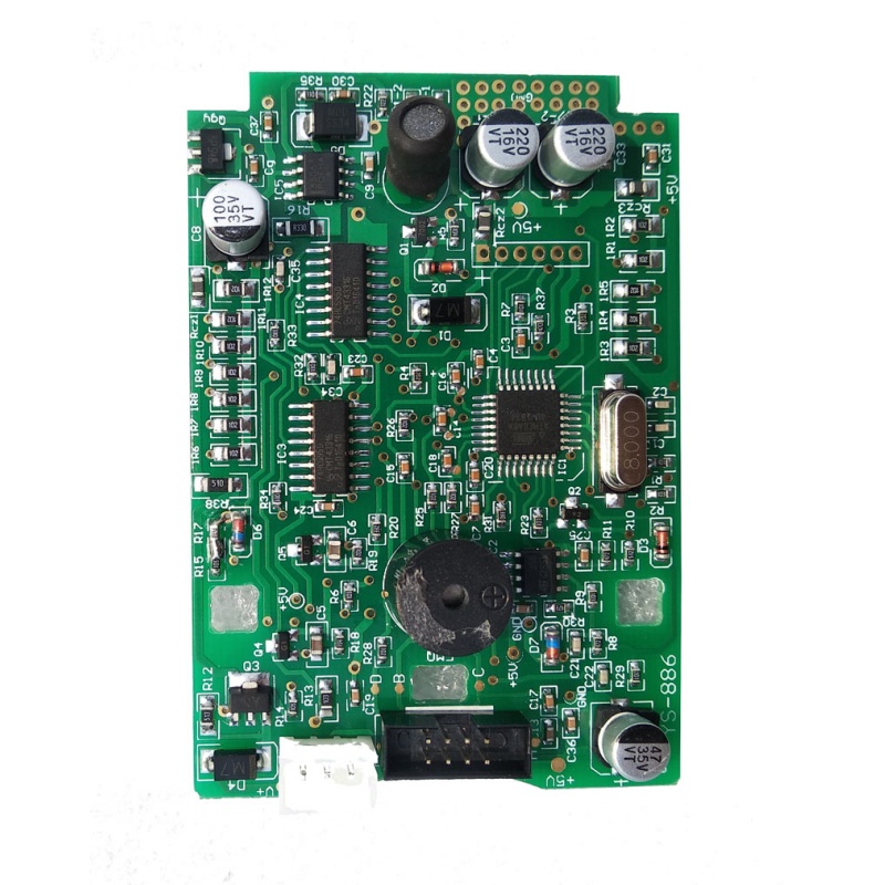
Custom Smart Device PCBA Assembly OEM PCB SMT Service
Integrated SMT control modules engineered for smart IoT nodes, home automation, and sensor-driven touch panels.
Explore SpecificationsFrom precision silver-printed PET matrix switches to rigid-flex user interface boards and thermal assemblies, explore our turnkey electronics manufacturing options.
Integrated SMT control modules engineered for smart IoT nodes, home automation, and sensor-driven touch panels.
Explore Specifications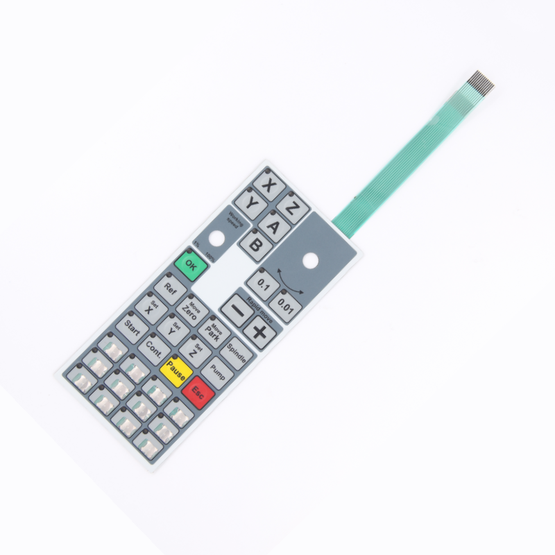
Screen-printed silver conductive ink circuit, custom graphic overlay, embossed tactile snap domes, and FPC/FFC tail.
Explore Specifications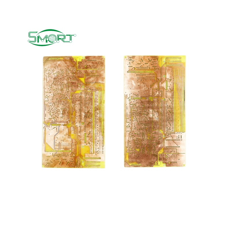
High-Tg FR4 rigid circuit substrate engineered for high-density matrix backplanes, multi-key controllers, and industrial modules.
Explore Specifications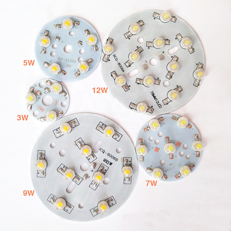
High thermal dissipation (1.5–3.0 W/m·K) aluminum core board with HASL/OSP finish for backlit membrane panels and indicators.
Explore Specifications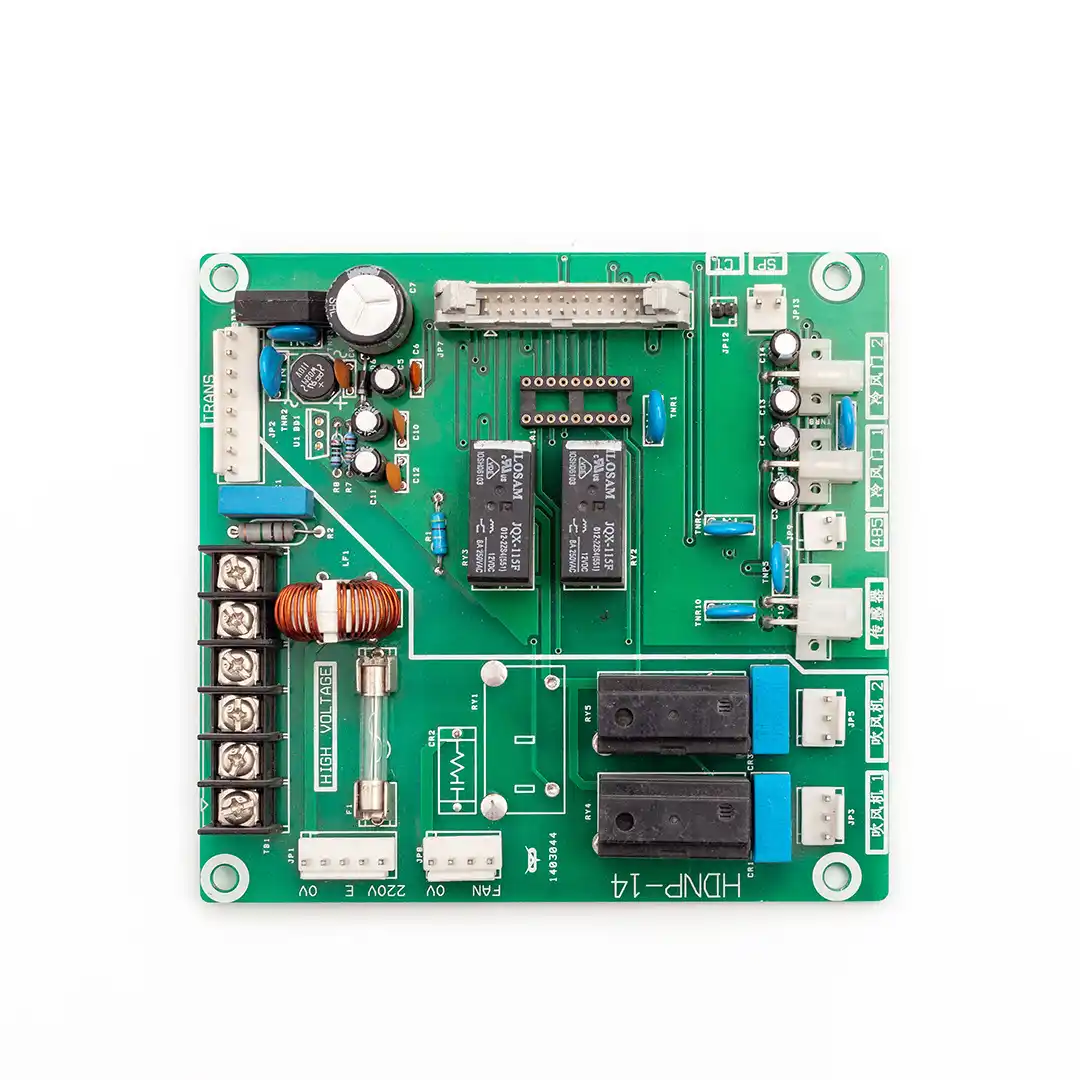
One-stop SMT and DIP manufacturing with 100% AOI, functional testing, and turnkey microcontroller decoding firmware flashing.
Explore Specifications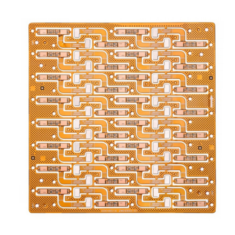
Polyimide (PI) flex circuits featuring rolled annealed copper traces, high-density ZIF tail terminations, and SMD LED mounting.
Explore Specifications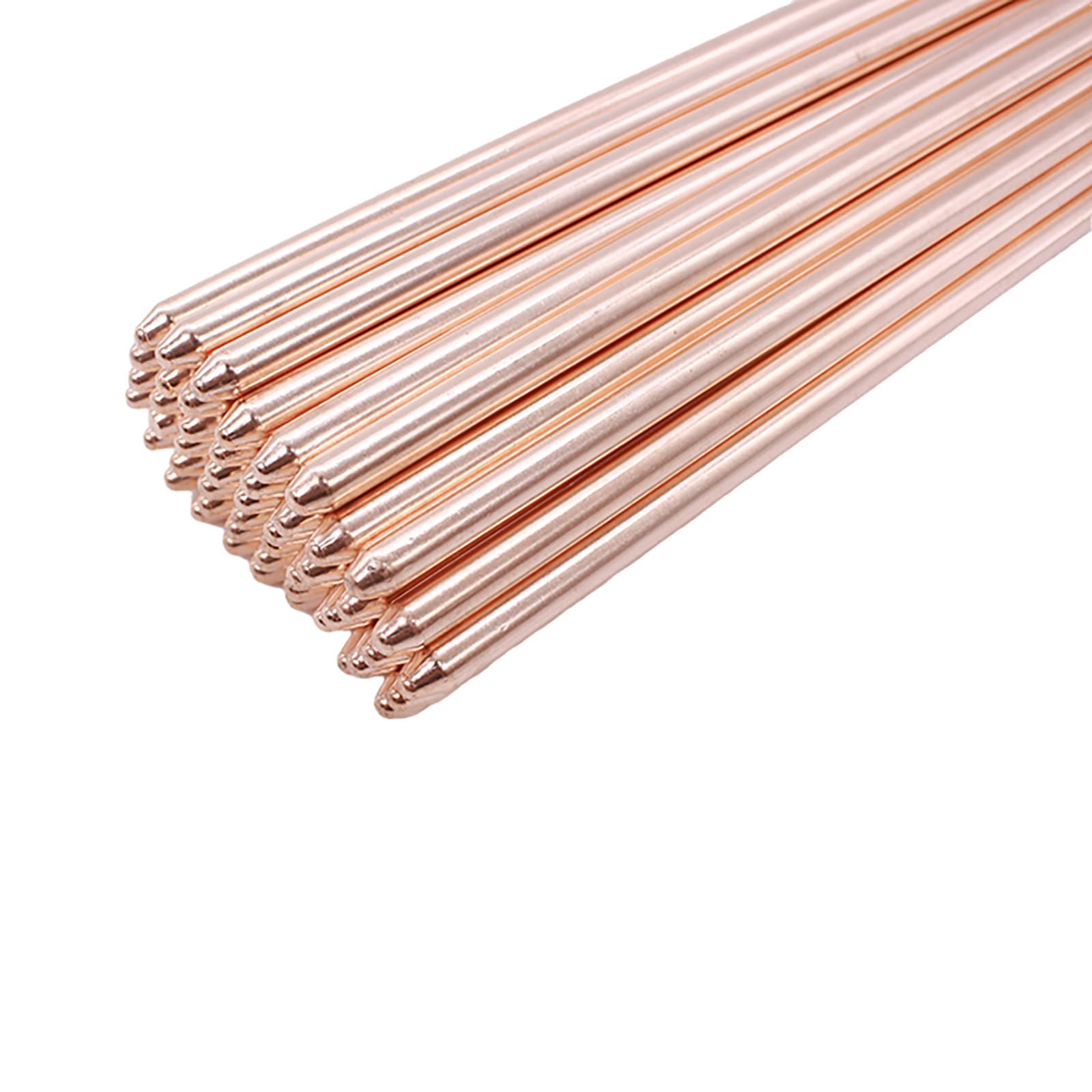
High-conductivity phase-change thermal heat pipe designed for enclosed industrial HMI panels and sealed operator terminal boxes.
Explore Specifications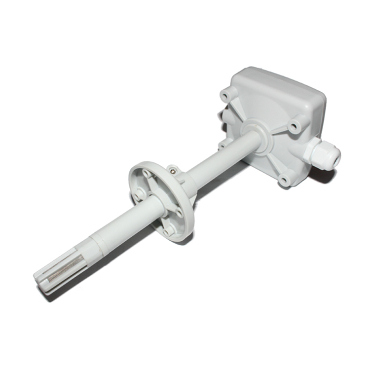
IP-rated protective housing for humidity/temperature sensors, designed to integrate seamlessly with matrix control faceplates.
Explore SpecificationsUnderstanding why matrix multiplexing dominates industrial human-machine interfaces over discrete pinouts.
In modern electronic apparatus engineering, human-machine interface (HMI) keypads demand an optimized balance among mechanical durability, tactile ergonomics, and microprocessor I/O consumption. Traditional discrete switch configurations necessitate one dedicated microcontroller GPIO per key along with a shared common return line—yielding an untenable N + 1 pin formula. When engineering user interfaces exceeding 8 to 16 keys (such as numerical inputs on medical infusion pumps, fuel dispensers, or programmable logic controllers), discrete topologies exhaust silicon resources, enlarge connector dimensions, and amplify PCB routing complexity.
The Matrix Membrane Keypad resolves this bottleneck via an orthogonal grid topology of intersecting Row (X) and Column (Y) conductors insulated by a die-cut dielectric spacer. Using an X × Y matrix configuration, an input array of 16 keys (a standard 4×4 keypad) requires merely 8 traces (4 rows + 4 columns) rather than 17. Extending this to a 6×6 array allows 36 independent switch locations using just 12 I/O pins, representing a 66.7% reduction in connector trace density.
Microcontrollers cycle Row lines sequentially (e.g., pulling Row 0 to logic LOW while keeping other rows HIGH with weak pull-ups) while concurrently evaluating Column inputs. Active state detection immediately decodes exact coordinate intersections (Row N, Col M) with typical hardware debounce filters calibrated between 10ms and 25ms to suppress contact bounce.
When an operator simultaneously depresses three keys forming three corners of an electrical rectangle, a parasitic circuit path bridges across the unpressed fourth corner, triggering an invalid "ghost key" signal. Shenzhen VUKO Electronics mitigates this through custom SMT surface-mount diode integration (1N4148 / BAS16) printed directly into the flex substrate layer, enforcing unidirectional conduction.
Conductive polymer thick-film (PTF) silver inks printed on heat-stabilized polyester (PET) provide cost-efficient performance with trace resistance calibrated under 100Ω. For harsh industrial applications requiring fine pitch (<0.5mm) or micro-SMD LEDs, VUKO deploys polyimide-based etched copper circuits (FPC) with gold immersion plating, offering virtually zero silver migration risk.
Deconstructing the 6 critical physical layers that govern tactile sensation, environmental seal, and chemical resilience.
A high-reliability matrix membrane switch is not a simple decorative label; it is a precision multi-layer composite engineered to endure cyclic mechanical shear, thermal contraction, and aggressive chemical cleaners. Each layer serves a decisive mechanical or electrical function:
| Layer Index | Component Layer | Material Composition | Nominal Thickness | Primary Functional Role |
|---|---|---|---|---|
| Layer 1 | Graphic Overlay | Autotex XE / F150 / F200 Textured PET or Makrofol PC | 0.125mm – 0.200mm | Sub-surface screen or digital printing; UV, chemical, and scratch barrier |
| Layer 2 | Overlay Adhesive | 3M 467MP / 3M 468MP High Performance Acrylic | 0.050mm – 0.130mm | Shear-resistant bonding between overlay and dome retainer sheet |
| Layer 3 | Dome Retainer & Vents | Optical PET Film with micro-vent channels | 0.075mm – 0.100mm | Secures tactile snap domes in axial alignment; equalizes pressure during actuation |
| Layer 4 | Dielectric Spacer | Biaxially Oriented PET with Double-Coated Adhesive | 0.125mm – 0.250mm | Defines tactile dome travel clearance; electrically isolates top/bottom traces |
| Layer 5 | Conductive Matrix Circuit | Conductive Silver Ink on Melinex PET or Copper/PI Flex (FPC) | 0.075mm – 0.125mm | Contains the X-Y matrix traces, contact fingers, and tail routing tracks |
| Layer 6 | Rear Mounting Adhesive | 3M 300LSE (for low surface energy plastics) or 3M 468MP | 0.130mm – 0.200mm | Hermetically bonds the complete keypad module to metal/plastic host enclosures |
Tactile discrimination directly impacts operator accuracy in high-stress medical, avionic, and field-work environments. Two primary tactile methods exist in modern matrix membrane fabrication:
Formed from high-tensile 301/304 stainless steel with nickel or gold plating. Offers actuation forces from 220g to 450g, a crisp "snap" tactile ratio of 40%–60%, and an extended operational lifespan rated up to 5,000,000 cycles.
Embossed directly into the polyester overlay or circuit substrate using precision heated tooling. Delivers smooth actuation, lower acoustic click, and a cost-effective design suitable for consumer electronics rated up to 1,000,000 cycles.
To prevent the ingress of cleaning fluids, saline solution, or rain, a continuous perimeter adhesive ring isolates internal contact zones. Internal micro-vent paths link key cavities together while venting internally to prevent diaphragm ballooning.
Integrated aluminum foil layers or printed conductive carbon-grid planes positioned above the matrix circuit dissipate static discharges up to 15kV, shielding sensitive microcontrollers from electro-static damage and RF interference.
Consolidating matrix switch printing, SMT pick-and-place, and multi-layer rigid PCB fabrication under one verified factory roof.
Procuring matrix membrane keypads from fragmented intermediaries frequently introduces engineering mismatches—such as mechanical flex tails that misalign with PCB headers, trace impedance variations that induce cross-talk, or adhesive failures caused by unvetted raw materials. As an Alibaba.com Onsite-Verified Supplier with over 14 years of direct export excellence, Shenzhen VUKO Electronics Co., Ltd. resolves these risks through an end-to-end, vertically integrated manufacturing model.
Comprehensive 24-hour review of artwork vector files, Gerber data, schematics, and mechanical step models. Traces, pitch, and dome spacing are checked to prevent short-circuits and silver migration.
Precision screen printing of graphic overlays and silver conductive circuits in temperature- and humidity-controlled cleanrooms, eliminating airborne particulate defects on transparent LCD windows.
Automated surface mount pick-and-place lines mount micro 0603/0805 indicator LEDs, series resistors, and anti-ghosting diodes directly onto flexible PET/FPC tails using conductive silver epoxy or reflow.
Laser plotter cutouts and matched male/female steel-rule die punch sets guarantee ±0.05mm perimeter dimensional tolerances, custom flex tail neck radii, and precise adhesive perimeter contours.
Automated computerized continuity fixtures verify contact loop resistance (<100Ω), insulation isolation (>100MΩ at 100V DC), LED forward voltage, and ensure zero opens, shorts, or misplaced domes.
Statistical batch validation across mechanical actuation endurance test rigs (>1M cycles), thermal cycling (-40°C to +85°C), and humidity chambers to certify long-term field stability before shipment.
Unlike conventional membrane-only print shops, VUKO's facilities house comprehensive printed circuit fabrication (1–12+ layers FR4, High-Tg, Aluminum MCPCB, Rigid-Flex), turnkey component procurement, and automated SMT/DIP lines. We deliver complete box-build integration: your graphic overlay, tactile dome matrix, rigid host backplane, display module, and housing ship under a single consolidated purchase order.
Strategic roadmap for procurement executives navigating capacitive migration, ultra-thin backlighting, and supply chain reshoring dynamics.
Modern industrial terminals increasingly pair the zero-power, fail-safe mechanical confirmation of metal snap domes with proximity capacitive touch sliders. Future matrix switches combine printed ITO or PEDOT:PSS touch electrodes alongside mechanical emergency stop or confirmation buttons on a unified flex substrate.
Eliminating uneven LED hot-spots without inflating panel thickness: 0.125mm Light Guide Films (LGF) harness side-firing micro LEDs and precision micro-dot extraction patterns to distribute uniform, low-power illumination across individual key icons, dead-front graphics, and corporate emblems.
Post-pandemic medical and commercial food processing specifications mandate specialized overlay chemistries (e.g., Autotex AM incorporating ionic silver additives). These permanently disrupt bacterial cell walls and withstand repeated wipe-downs using isopropyl alcohol, bleach, and quaternary ammonium compounds without crazing.
Procurement engineers must weigh Non-Recurring Engineering (NRE) tooling charges against production yields and environmental exposure. The table below delineates the empirical cost-performance trade-offs:
| Evaluation Parameter | Silver Conductive Ink on PET Film | Etched Copper on Polyimide (FPC) | Rigid FR4 Backer PCB Matrix |
|---|---|---|---|
| Initial NRE / Tooling | Low ($150 – $350 film/die tooling) | Moderate ($300 – $600 phototooling) | Moderate to High ($250 – $800 drill/rout tooling) |
| Unit Economics at Scale | Extremely cost-effective for >500 pcs | Balanced for complex micro-circuitry | Higher material cost per cm² |
| Connector Pitch Capability | Standard 2.54mm, 1.27mm minimum | Ultra-fine pitch down to 0.5mm / 0.3mm ZIF | Any standard board-to-board or header |
| Trace Loop Resistance | 10Ω – 100Ω (dependent on trace run) | < 1Ω (negligible voltage drop) | < 0.5Ω (ideal for power routing) |
| Bending & Dynamic Flex | Good (static radius >5mm recommended) | Exceptional (dynamic hinge flex endurance) | Rigid (zero flexural tolerance) |
| SMD LED Assembly Method | Conductive silver epoxy encapsulation | Standard automated SMT reflow soldering | Standard SMT reflow / through-hole DIP |
Direct engineering answers to critical supplier qualification, testing, and file delivery questions.
Submit your artwork files, Gerber layouts, or physical samples. Our engineering team conducts a thorough DFM and circuit audit, returning an itemized quote within 24 hours.